Innovative ideas make it possible to simplify many processes, add convenience when using household and industrial equipment, and automate work cycles.
Often, a contactless switch is taken to implement them, able to react in a timely manner to a specific stimulus without the physical presence of a person.
Let's take a closer look at what kind of device it is and for what purpose it serves.
What is a proximity switch for?
To perform a certain action, it is not necessary to take an active part yourself - go to the intended object and carry out any manipulations with it. A smart product offered by manufacturers of electrical equipment is capable of partially replacing a person.
The principle of operation of the equipment
A device that stops the operation of certain equipment in a non-contact manner is called a switch or, in short, WB. It is also often called a sensor - but this concept generalizes in itself also devices with an analog output signal.
Such terminology, as well as the scope of use, resistance to various kinds of damage and technical specifications are provided GOST R 50030.5.2-99. The document regulates the compliance of operating parameters, the timely operation of the protective mechanism during overload and other operational nuances of the device.
The product is a semiconductor element that controls the electrical circuit. If an irritant is detected or is present in the zone of its action, it turns off the load current, which leads to an open circuit.
The device has a robust housing made of polymer or nickel-plated brass. Inside such an enclosure is an electrical part that needs insulation. Many models have protection class IP65 or 67.

The structure of the product involves the detection of an object or object that has fallen into the active zone. This information is converted and fed to the switching node.
The device works without contact, and the sensitive element, also called a photodetector, can be located separately from the emitter or in the same housing with it. These 2 parts work in pairs.
As for the size, shape and appearance of the WB, these parameters depend on the purpose and scope of application, as well as operating conditions.
The standard provides for the manufacture of devices, the shape of the case of which is as follows:
- rectangular with a square or rectangular section, which is denoted as D or C, respectively;
- cylindrical with thread - A or without it - B.
Depending on the model and its intended use, the product can be additionally equipped with a cable coated with double insulation.
To operate in difficult conditions, contactless devices are produced, the housing of which is flooded with a compound. This is a polymeric substance that provides reliable protection against moisture and other foreign matter getting on the working mechanisms.
According to the principle of functioning, the devices are divided into 4 broad groups.
Image Gallery
Photo from
Inductive proximity sensor
Capacitive Switch Type
Ultrasonic contactless switch
Photoelectric proximity sensor
The capacitive and inductive detection method is more reliable, and the WB itself, working in this way, are more durable than their counterparts. The first of them respond to an item made of almost any material, and the second to metal.
Scope of contactless device
The unique property of controlling the operation of devices without contacting them directly opens up bright prospects for the use of this type of switch. It allows you to create original developments in various fields, improve living conditions in a house / apartment.

Turning off the light without contact of the owner with the housing or other elements of the switching device is a reality. For the product to execute this command, it is sufficient to place the hand in the impact zone
And for sound modifications, it is enough to clap your hands so that the device hidden inside the chandelier body opens the circuit.
In addition, proximity sensors are widely used to optimize production processes. It is they that allow you to control the quality of the implementation of complex cycles in mechanical engineering.
And also on automatic lines in the production of food products and textile products, in the manufacture of parts in foundries, and more.
Image Gallery
Photo from
Huge production areas with heavy equipment can work smoothly due to process control by switches that will timely disconnect the load in the event of an error or an overload
Amateur radio innovators who invent robotics and think through the automation of many actions often use non-contact type sensors, installing them in their designs
In the manufacture of products using forge-and-press equipment, foundry machines or automatic lines, where it is impossible for the human eye to keep track of each element, one cannot do without reliable WB
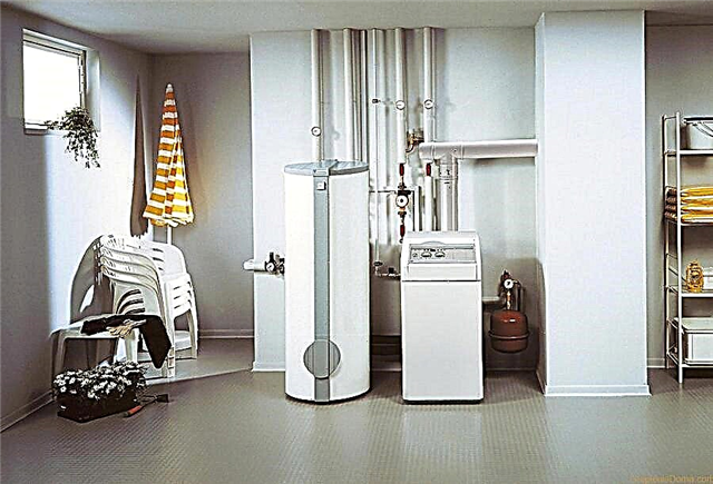
In everyday life - to improve the quality of life at home. This is the power cut to the hand dryer, the lamp in the corridor, the fan in the bathroom, the boiler
Contactless switches in mechanical engineering
Proximity sensors in robotics
Contactless circuit breakers on automatic lines
Proximity sensors in the home
What will the labeling say?
Non-contact type switches are supplied to the market by various manufacturers. Among them are Western, domestic and Chinese companies. It is important when buying to pay special attention to the quality of the units and the reputation of the manufacturer.
Due to the seriousness of the regulated processes, for the control of which various modifications of the sensors are used, you should only choose products that have accompanying documentation - instructions with installation diagrams, operating conditions and a list of technical parameters.

On the case of the device itself, manufacturers indicate its characteristics in the form of a set of letters and numbers - mark it. Among these designations, a part of important information is encrypted, which is guided by when choosing the right model
Not all indicators can fit in a small section of the switch. The rest, relevant to the consumer, are contained in the user manual.
If the model you like does not have instructions in the kit, then you should not buy it - it could be a fake. Moreover, some of the required parameters will remain unknown, but you cannot trust the seller.

All manufacturers are required to provide end-user specifications. This requirement is prescribed in part 5-2 of the GOST on low-voltage non-contact equipment mentioned above
Each company engaged in the production of switching devices for controlling an electric circuit has its own notation system. Its decoding is given in the catalog, which also contains the range of products offered.

An example of product labeling from AS Energy. The remaining parameters of the models are placed in the instructions supplied
The need for marking arose by chance - the variety of circuit breakers is large. In addition, they can be classified according to various principles.
For example, depending on the function performed during switching, devices are divided into the following categories:
- inclusion (NO) - A;
- shutdown (NF) - B;
- switching - C;
- programmable option - P;
- another - S.
And according to the installation method, the sensors are recessed, unrecessed, and others.

Sometimes manufacturers prefer to indicate a long cipher, which describes the maximum parameters of the product, including the location of the sensitive element, the presence of indications, climate performance, etc.
If the company uses the labeling principle recommended by GOST, then the inscription on the switch will have, for example, the following form:
U3 A30 A D2
Where:
- U is an ultrasonic method for detecting an irritant. The rest correspond to other Latin letters: I - inductive, C - capacitive, D, R and T - photoelectric direct, reflective and barrier action, respectively;
- 3 - another installation method;
- A30 - shape and diameter, which in this case means cylindrical with a thread with a diameter of 30 mm;
- A is the switching function of the element, which means the inclusion of (NO);
- D is the number of wires for outputting direct or alternating current, which corresponds to two connectors for direct current;
- 2 - plug-in connection method.
In total, 4 matching options are provided, among which the unit corresponds to ribbon wires, the two are considered above, the three are clamped, and the four are another method.

In versions involving the presence of a wire, the manufacturer applies the characteristics to the label, which is mounted directly on the cable. It can also indicate the degree of protection, recommended voltage, and more.
Among bona fide manufacturers there are such companies as Sensor / Sesor, German company Fotoelektrik Pauly, NPK TEKO, PKF STRAUS, Meander CJSC, OVEN and SKB IS, NPP PRIZMA from Yekaterinburg and others.
Many of them offer a service for manufacturing WB with the parameters that are necessary for the consumer - to order.
We also recommend reading our other article, where we described in detail the various types of light switches. Read more - read on.
DIY connection features
It is possible to install a contact switch for domestic use, functioning non-contact. As for the models for controlling the load current in production, here only an employee who has access to specific equipment is allowed to carry out installation.

It is necessary to carefully consider the purchase - the switch is completed with instructions, fasteners, sometimes lock nuts. All this will come in handy.
Before connecting, pay attention to the following points:
- for the functioning of the WB requires power, but it can not be connected directly if the product is a two-wire type;
- at the power source used for the proximity sensor, the voltage must correspond to the parameters specified in the switch passport;
- When tightening fasteners, it is important not to overtighten the nuts.
The manual should include a wiring diagram to be followed, as well as a method for installing a specific model.

Installation options are completely dependent on the features of the purchased modification. It is important to use the method specific to the purchased sensor.
First, a mechanical type of installation is performed - using fasteners, if necessary, lock nuts to connect the device.
When everything is securely fixed, then it's time to proceed to the second stage - the electrical connection.

The wiring diagram depends on whether direct or alternating current is used. The number of wires also affects the choice of circuit - here you need to be careful to correctly connect the existing cables
When working with the mains, it is important not to forget to turn off the power on the apartment panel to protect yourself. Then the WB wire is connected in one of the ways provided by GOST. Its type depends on the modification.
Most often, for home use, they buy a sensor that controls the operation of the chandelier. Therefore, the last stage is the placement of the fixture in the body of the lighting product. If necessary, adjust and configure the response time, the active distance at which the device will operate.
Assembling the device at home
You can make a switch yourself. Although at first glance, this venture seems complicated and incomprehensible to the average consumer, but if desired, everything will work out if you choose a simple method.
The best part is that a person who does not have much experience in assembling electrical appliances, but is keenly interested in such units, will be able to cope with the task.
Of course, if you do not aim at creating a device capable of performing programmable switching of an element, when complex response options are implemented.

The easiest option is to make a switch that detects an object at a distance of several centimeters and opens a contact at that moment. It can be a light bulb, fan or other control unit
The product should be able to turn off the light bulb if the user's hand falls into the coverage area for a couple of seconds.
First you have to prepare the working elements for the assembly of the device. It will be a board, microcircuit, transistors, relays, capacitors, LEDs, photocells and other accessories.
Image Gallery
Photo from
A good option is to buy a ready-made set of components so as not to be assembled in parts on the market. Moreover, the Chinese are very inexpensive to sell
It is necessary to take the circuit that comes with the parts, consider it carefully and put each of the spare parts in the place assigned to it
Each element inserted on the board has legs, the length of which significantly exceeds the required. Therefore, the tips on the back are better to bite off and bend
Now you have to work with a soldering iron - well, if there is such an experience. Otherwise, it is advisable to practice the draft, and then solder each connection
Having coped with part of the work, you need to put the rest of the LEDs, capacitors and other parts in the places reserved for them. On the board you can see the notation
It was the turn to put the relay, following the recommendations given in the layout of the components of the assembly. Solder thoroughly
A photodiode coated with black plexiglass is installed on a portion of the board designated as RX (receiver). And in place with the inscription TX (transmitter) - a transparent LED. For these parts, a longer leg is responsible for plus
Now the chip is placed on the rectangle defined by it, which is indicated in the instructions. Using a soldering iron, it is securely fastened so that nothing hangs and does not go to the sides
A good option is to buy a ready-made set of elements.
Bend the ends of the legs of the elements
Solder each connection
Put the remaining parts
Put and solder the relay
Install photodiode and LED
After soldering, it is necessary to check the quality of the joints made so that each structural element is securely fixed.
The lifetime depends on this, because the product will be placed inside the fan housing, hand dryer or chandelier.
Image Gallery
Photo from
The main thing is not to confuse the keys when installing the chip - you will carefully examine its placement in the instructions
The contactless device requires electricity. Therefore, you need to connect the power supply to the board without confusing the plus and minus contact on it
After completing the assembly and soldering, you can conduct testing. To do this, check the operation of the switch by running a hand over the structure - the indicators should light up
You can adjust the time delay off by reducing it or increasing as you wish, or the range of response to the stimulus
To add a little functionality, you have to buy another chip, for example, CD4013BE or any other 4013 series. It is better not to take a domestic one, preferring a foreign one. Still need one resistance / resistor at 10 kOhm
Now you need to solder the resistor, then connect the plus and minus wires, and a 10 kOhm resistor to the output leg number 13
Having carefully considered the circuit, you should determine on the board where the plus and minus from the additional chip should be soldered
Posting from 14 legs should go to the plus indicated earlier, and from 7 legs will go negative posting, which also needs to be soldered. This is indicated in the instructions of the chip
The main thing is not to mix up the keys when installing the chip
connecting the power supply to the board
Health Check
Instrument response time adjustment
Another chip CD4013BE
10 kOhm resistor soldered to the chip
Determining the plus and minus on the board
Solder the plus and minus wires to the board
It remains to verify the operability of the assembled device. To do this, carry out several tests for operation, holding the palm next to the sensor.

If the result is satisfactory and the design has passed the test, then it can be placed in the housing of a lamp, chandelier, dryer or other equipment and connected according to the scheme
When the result is not satisfied, it is up to the adapter - a screw for adjustment - to set the necessary parameters for the response.
The assembled circuit breaker can be further modified by adding the desired functions if there is experience in conducting electrical work and the desire to create something original.
Why do we need non-contact switching devices, their types, connection and marking:
An infrared switch helps turn on the light without touching the actual keys of the switching device. Assembly and demonstration of his work in the video:
About capacitive switches operating without direct contact with an object:
Having dealt with the intricacies of marking and the scope of application of specific types of sensors, you can choose the optimal model for switching electrical circuits. Or even make a contactless assembly yourself, having acquired a set of necessary elements with a diagram for their location. Such a switch will make your home a little “smarter”.
Want to ask a question about mounting a proximity switch? Please leave comments in the block below. Here you also have the opportunity to report an interesting fact on the topic of the article.