Heating systems in their modern form are complex structures equipped with different equipment. Their effective work is accompanied by optimal balancing of all the elements included in their composition. Hydroarrow for heating is designed to provide balance. Its principle of action is worth sorting out, do you agree?
We will talk about how the hydraulic separator works and what advantages the heating circuit equipped with it has. The article we presented describes the installation and connection rules. Useful operating instructions are provided.
Hydraulic Flow Separation
Hydroarrow for heating is often called a hydraulic separator. From this it becomes clear that this system is intended for implementation in heating circuits.
In heating, it is assumed to use several circuits, for example, such as:
- lines with groups of radiators;
- underfloor heating system;
- hot water supply through a boiler.
In the absence of a hydraulic arm for such a heating system, one will have to either make a carefully calculated design of each circuit, or equip each circuit with an individual circulation pump.
But even in these cases, there is no complete certainty of achieving an optimal balance.

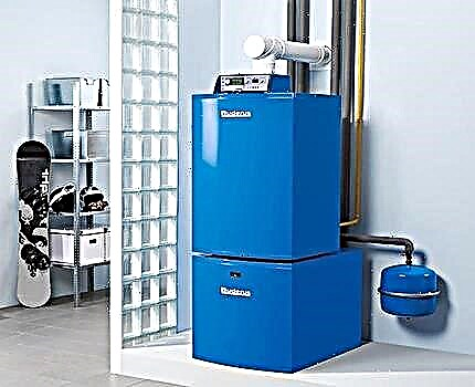
Something like this can be considered the classic design of hydraulic dividers made on the basis of round or rectangular pipes. A simple but effective solution that fundamentally changes the state of the heating system with the participation of the boiler
Meanwhile, the problem is solved simply. It is only necessary to apply a hydraulic separator in the circuit - a hydraulic arm. Thus, all the circuits included in the system will be optimally separated without the risk of hydraulic losses in each of them.
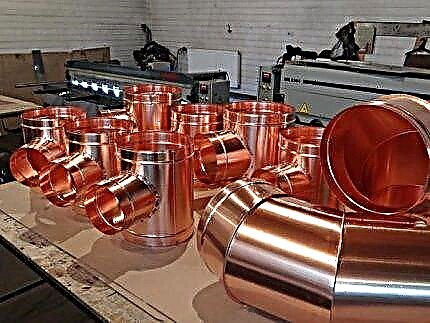
Hydroarrow - the name "everyday". The correct name corresponds to the definition - "hydraulic divider". From a structural point of view, the device looks like a piece of a regular hollow pipe (round, rectangular sections).
Both end sections of the pipe are drowned out by metal pancakes, and there are inlet / outlet pipes (on a pair on each side) on different sides of the casing.

The natural appearance of the products is hydraulic arrows made of a pipe of rectangular cross section and round. Both options show high efficiency. However, round pipe based water guns are still considered the more preferred option.
Traditionally, the completion of installation work on the installation of the heating system is the beginning of the next process - testing. The created plumbing design is filled with water (T = 5 - 15 ° C), after which the heating boiler is started.
Until the coolant is warmed up to the required temperature (set by the boiler program), the water flow is “turned” by the primary circulation pump. The secondary circulation pumps are not connected. The coolant is directed along the hydraulic arrow from the hot side to the cold side (Q1> Q2).
If the coolant reaches the set temperature, the secondary circuits of the heating system are activated. The coolant flows of the primary and secondary circuits are aligned. Under such conditions, the water gun functions only as a filter and an air vent (Q1 = Q2).

Functional diagram of the classic hydraulic arrow for three different boiler operation modes. The diagram clearly indicates the distribution of heat fluxes for each individual operating mode of boiler equipment
If some part (for example, the underfloor heating circuit) of the heating system reaches the set heating point, the selection of the coolant by the secondary circuit is temporarily stopped. The circulation pump is switched off automatically, and the water flow is directed through the hydraulic arrow from the cold side to the hot side (Q1 The main reference parameter for the calculation is the velocity of the coolant in the section of vertical movement inside the hydraulic arrow. Usually the recommended value is not more than 0.1 m / s, under any of two conditions (Q1 = Q2 or Q1 The low speed is due to quite reasonable conclusions. At this speed, the debris (sludge, sand, limestone, etc.) contained in the water stream manages to settle on the bottom of the pipe of the water gun. In addition, due to the low speed, the necessary temperature head manages to form. Two structural types of hydraulic arrows, which are usually calculated: 1 - in three diameters; 2 - on the alternation of nozzles. Regardless of the adoption of a particular methodology, the basic calculation parameters are always typical - the flow rate of the coolant along the contours and the speed parameter The low transfer rate of the coolant contributes to a better separation of air from water for subsequent output through the air vent of the hydraulic separation system. In general, the standard parameter is selected taking into account all significant factors. For calculations, the so-called technique of three diameters and alternating nozzles is often used. Here the final design parameter is the value of the diameter of the separator. Based on the obtained value, all other required values are calculated. However, to know the size of the diameter of the hydraulic separator, you need data: In fact, these data for the calculation are always available. For example, the flow rate in the primary circuit is 50 l / min. (from the technical specifications of pump 1). Secondary flow rate is 100 l / min. (from the technical specifications of pump 2). The diameter of the hydraulic arrow is calculated by the formula: The formula for calculating the diameter of the pipe of a water gun depending on the parameters of the coolant flow rate (flow rate according to the characteristics of the pump) and the vertical flow rate where: Q - the difference in costs Q1 and Q2; V is the velocity of the vertical duct inside the arrow (0.1 m / sec.), Π is a constant value of 3.14. Meanwhile, the diameter of the hydraulic separator (conditional) can be selected using the table of approximate standard values. The height parameter for a heat flux separation device is not critical. In fact, the height of the pipe can be taken any, but taking into account the supply levels of incoming / outgoing pipelines. The classic version of the hydraulic separator involves the creation of nozzles symmetrically located relative to each other. However, a schematic version of a slightly different configuration is also practiced, where the nozzles are located asymmetrically. What does it give? The manufacturing scheme of the hydraulic separator, in which the nozzles of the secondary circuit are somewhat offset relative to the nozzles of the primary circuit. According to the inventors (and proved by practice), this option seems to be more productive in particle filtration and air separation As the practical application of asymmetric schemes shows, in this case there is a more efficient separation of air, and better filtration (sedimentation) of suspended particles present in the coolant is also achieved. The classical circuitry defines the supply of four pipelines to the design of the hydraulic separator. This inevitably raises the question of the possibility of increasing the number of inputs / outputs. In principle, such a constructive approach is not excluded. However, the efficiency of the circuit decreases with increasing number of inlets / outlets. Consider a possible option with a large number of nozzles, unlike the classics, and analyze the operation of the hydraulic separation system for such installation conditions. Separator circuit of multichannel distribution of heat fluxes. This option allows you to serve more voluminous systems, but if the number of nozzles increases by more than four, the efficiency of the system as a whole decreases sharply In this case, the heat flux Q1 is completely absorbed by the heat flux Q2 for the state of the system, when the flow rate for these flows is practically equivalent: Q1 = Q2. In the same state of the system, the heat flux Q3 in terms of temperature is approximately equal to the average values of Tav. Flowing along the return lines (Q6, Q7, Q8). At the same time, there is a slight temperature difference in the lines with Q3 and Q4. If the heat flux Q1 becomes equal in terms of the heat component Q2 + Q3, the temperature head distribution is noted in the following relationship: T1 = T2, T4 = T5, whereas T3 = T1 + T5 / 2. If the heat flux Q1 becomes equal to the sum of the heat of all other flows Q2, Q3, Q4, in this state all four temperature heads are equalized (T1 = T2 = T3 = T4). A multi-channel dividing system with four inputs / four outputs, quite often used in practice. For servicing heating systems of a private household, this solution is quite satisfactory in terms of technological parameters and stabilization of the boiler In this situation, on multichannel systems (more than four), the following factors are noted that have a negative impact on the operation of the device as a whole: It turns out that the departure from the classical scheme with an increase in the number of branch pipes almost completely eliminates the working property, which a gyroshooter should have. The design of the arrow, where the presence of the functions of an air separator and a filter settler is excluded, also somewhat deviates from the accepted standard. Meanwhile, on such a design, two flows with different speeds of movement (dynamically independent circuits) can be obtained. A non-standard design solution for the manufacture of a hydraulic arrow. It differs from the classics in that there are no functions of filtration and air outlet. In addition, the distribution of heat fluxes has a perpendicular transport scheme, thereby achieving speed isolation For example, there is the heat flow of the boiler circuit and the heat flow of the circuit of heating appliances (radiators). With a non-standard design, where the flow is perpendicular, the flow rate of the secondary circuit with heating devices increases significantly. On the contour of the boiler, on the contrary, the movement is slowed down. True, this is a purely theoretical view. It is practically necessary to test in specific conditions. The need for a classic design of the hydraulic separator is obvious. Moreover, on systems with boilers, the introduction of this element becomes mandatory. The installation of a hydraulic pump in the system serviced by the boiler ensures the stability of the flows (coolant flow). As a result, the risk of water hammer and temperature surges is completely eliminated. Examples of hydraulic guns in a classic simple design based on plastic piping. Now such structures can be found even more often than metal ones. The efficiency is almost the same as that of metal, but the fact of saving on the device and implementation in the system For any ordinary water heating system made without a hydraulic separator, disconnection of part of the lines is inevitably accompanied by a sharp increase in the temperature of the boiler circuit due to the low flow rate. At the same time, the return of a strongly cooled backflow takes place. There is a risk of water hammer formation. Such phenomena are fraught with a quick failure of the boiler and significantly reduce the service life of the equipment. For household systems, in most cases, plastic structures are well suited. This application is seen to be more economical in installation. In addition, the use of fittings makes it possible to install the system from polymer pipes and connect plastic hydraulic guns without welding. From a service point of view, such solutions are also welcome, as the hydraulic divider mounted on the fittings is easy to remove at any time. Video about practical application: when there is a need to install a water gun, and when it is not needed. It is difficult to overestimate the importance of the hydro-arrow in the distribution of heat fluxes. This is really necessary equipment that should be installed on each individual heating and domestic hot water system. The main thing is to correctly calculate, design, fabricate a device - a hydraulic divider. It is the exact calculation that allows you to achieve maximum return on the device. Please write comments in the block below, post a photo on the topic of the article, ask questions. Tell us about how the heating system was equipped with a hydraulic arrow. Describe how the operation of the network changed after it was installed, what advantages the system acquired after including this device in the circuit.Design parameters of a hydroarrow


Boiler power value, kW Inlet pipe, mm Diameter of a hydroarrow, mm 70 32 100 40 25 80 25 20 65 15 15 50 Circuit solution for the shift pipes

The number of connections on the hydraulic arrow


Hydraulic separator without filter

What is the use of a hydraulic arrow?